Tesla Wall Connector Installation Manual: Gen 2 vs Gen 3
-
Share
Whether you just bought a Tesla Wall Connector or you’re planning ahead before purchase, getting your hands on the right tesla wall connector installation manual matters. Tesla has released multiple generations of this home charger, Gen 2, Gen 3, and the newer Universal Wall Connector, and each one comes with different wiring requirements, configuration steps, and software features. Mixing up the details between generations can lead to real problems during setup.
This guide breaks down the installation documentation for each version so you know exactly what applies to your unit. We’ll cover the key differences in electrical specs, mounting procedures, commissioning steps, and Wi-Fi configuration that distinguish Gen 2 from Gen 3 and the Universal model. You’ll also find direct links to Tesla’s official manuals and practical notes on what the documentation doesn’t always make obvious, the kind of thing you pick up after thousands of EV charger installations, not from reading a PDF once.
At Advance Solar & Spa, we’ve been installing solar energy systems, battery storage, and EV charging stations across Florida since 1983. As a Tesla Certified Installer with a full in-house team of licensed electricians, we work with every generation of Wall Connector on a regular basis. That hands-on experience with over 50,000 installations is what shaped this article, so the guidance here goes well beyond what’s printed in the box.
Before you start: safety, skills, and permits
A Tesla Wall Connector runs on a 240-volt dedicated circuit, which puts it in a different category than most household electrical work. A wiring mistake that simply trips a breaker on a 120V outlet can ignite a fire when it happens on a 240V line. Before you open the tesla wall connector installation manual or pick up a screwdriver, you need an honest assessment of your skills, your panel capacity, and what your local jurisdiction requires before work begins.
Know your skill level before you start
Tesla designs the Wall Connector for installation by a licensed electrician, and the official documentation states that directly. That doesn’t mean a homeowner with solid electrical experience can’t handle the prep work, but the final connection to the service panel and breaker termination should involve someone holding a valid electrical license. In most states, including Florida, making live connections to a residential service panel without a license is a code violation regardless of your personal skill level.
Your realistic role as a homeowner is to plan the conduit path and material list, understand the specs so you can communicate clearly with your electrician, and confirm the panel has available capacity. That preparation cuts labor time and reduces surprises on installation day.
Permits and why skipping them creates problems
Most jurisdictions require an electrical permit for any new 240V circuit, and EV charger installations fall squarely in that category. Skipping the permit creates two serious problems: your homeowner’s insurance policy may deny a claim tied to an unpermitted electrical installation, and an unpermitted circuit can stall or kill a home sale.
Pulling a permit means an inspector verifies the completed work, which is a layer of protection for you, not just a formality for the jurisdiction.
Contact your local building department before you schedule installation. The permit application typically needs the circuit amperage, breaker size, wire gauge, and the charger’s make and model. Tesla’s documentation provides all of that data, so have the correct generation’s manual available when you complete the form.
Safety steps before any work begins
No one should touch the Wall Connector’s wiring without completing each of these steps first:
- Turn off the correct breaker or the main breaker, then confirm the circuit is dead with a non-contact voltage tester before touching any conductors
- Lock out the panel if other household members are present so no one accidentally restores power mid-job
- Keep the work area completely dry and identify any water sources near the planned mount location
- Wear insulated gloves rated for 1000V whenever you work inside or near the panel enclosure
- Verify the circuit is de-energized at the wire end, not just by reading the breaker label
Wall Connectors also generate real heat during extended charging sessions, so mounting surface material and required clearances are safety considerations, not just code checkboxes. The planning steps that follow cover both.
Step 1. Identify your Wall Connector and match the manual
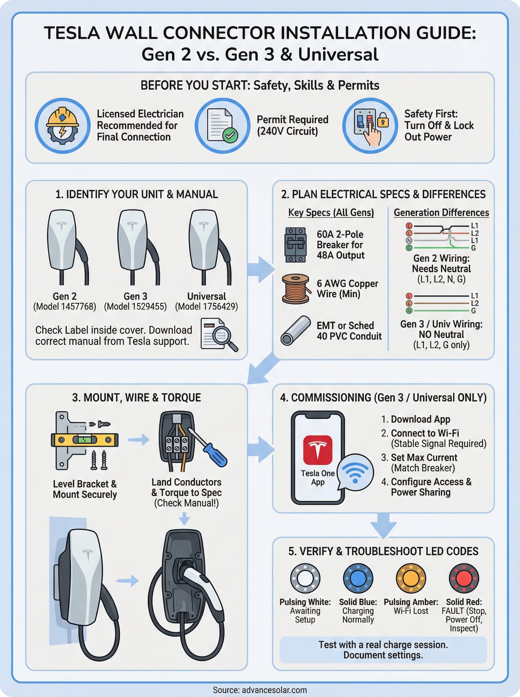
Before you open any version of the tesla wall connector installation manual, confirm exactly which unit you have. Tesla has shipped three distinct generations, and using the wrong documentation creates real problems: wiring diagrams won’t match your terminal layout, torque specs will be off, and the commissioning steps for a Gen 3 simply don’t exist in the Gen 2 guide. Getting the generation right is the entire point of this first step, and it takes less than two minutes if you know where to look.
How to read the label on your unit
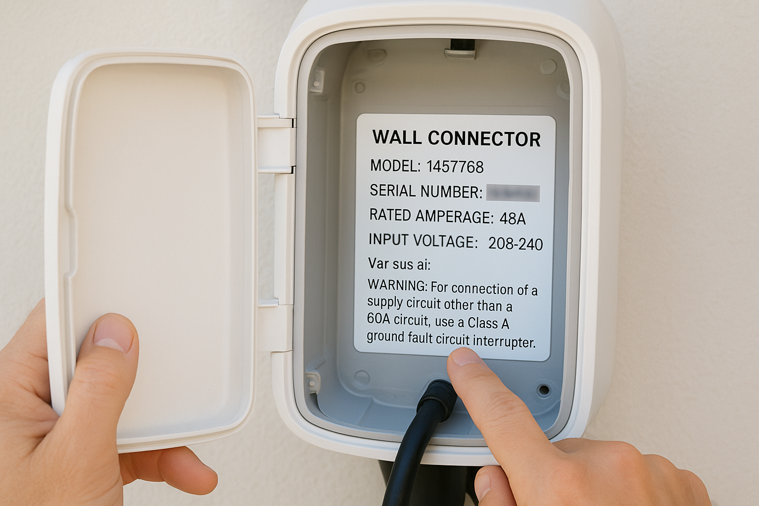
Every Wall Connector has a product label on the inside of the cover, visible once you remove the front panel. That label carries the model number, serial number, rated amperage, and input voltage. Use the model number to confirm your generation:
| Generation | Model Number Prefix | Max Output | Wi-Fi Required |
|---|---|---|---|
| Gen 2 | 1457768 | 48A / 11.5kW | No |
| Gen 3 | 1529455 | 48A / 11.5kW | Yes (for setup) |
| Universal | 1756429 | 48A / 11.5kW | Yes (for setup) |
If the model number on your label doesn’t match one of these prefixes, search the full model number on Tesla’s support site before proceeding with any wiring.
The serial number on that same label also matters because Tesla uses it to link your device to your account during Gen 3 and Universal commissioning. Photograph both the model number and the serial number before you reinstall the cover.
Where to find the correct official manual
Tesla hosts current installation guides directly on their support site at tesla.com/support. Search for “Wall Connector installation guide” and filter by generation. Each PDF includes the wiring diagram, conduit entry points, torque specs, and configuration instructions specific to that unit. Download the correct version and keep it accessible throughout the install. Printed copies work better on a job site than a phone screen, particularly when both hands are occupied inside the enclosure.
Step 2. Compare Gen 2 vs Gen 3 so you plan correctly
Understanding the differences between generations before you finalize any part of the installation plan will save you from having to redo work. The wiring terminal layouts, commissioning requirements, and power-sharing capabilities are different enough between Gen 2 and Gen 3 that treating them as interchangeable causes real mistakes. The tesla wall connector installation manual for each generation reflects those differences in detail, so confirm which guide matches your unit before you move forward.
Key hardware differences
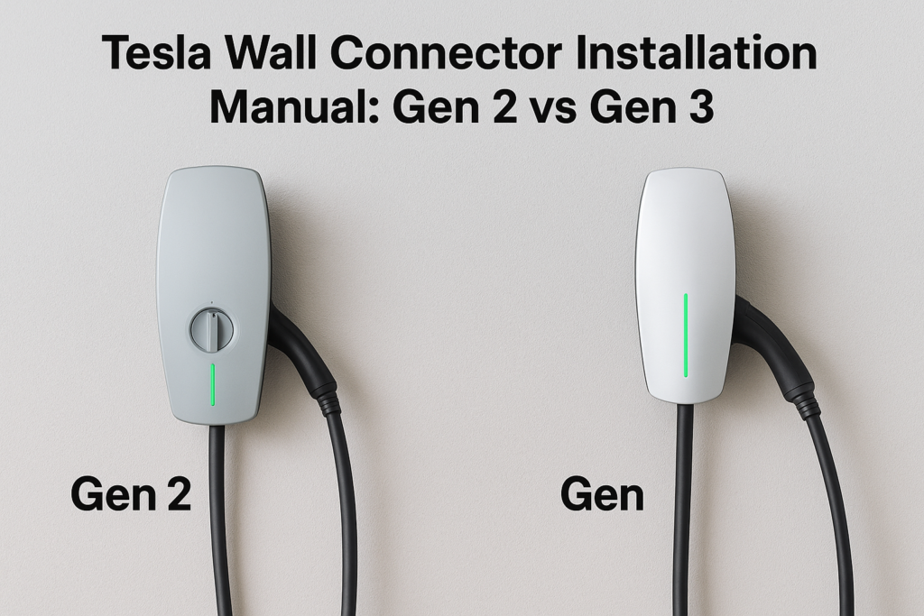
The physical units look similar from the outside, but the internal terminal blocks and conduit entry points are not identical. Gen 2 uses a simpler terminal layout with separate connections for line, neutral, and ground. Gen 3 introduces a different terminal block configuration that accepts larger conductor sizes and includes a dedicated port for the Wi-Fi antenna assembly. Conduit entry positions also shifted between generations, so the cable path you plan for one will not necessarily route cleanly to the other.
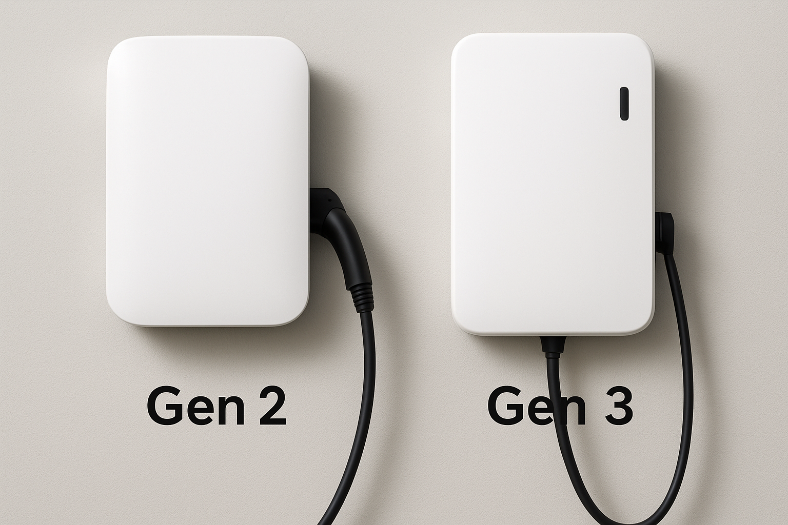
| Feature | Gen 2 | Gen 3 / Universal |
|---|---|---|
| Max circuit breaker | 60A | 60A |
| Max continuous output | 48A | 48A |
| Wi-Fi required for setup | No | Yes |
| Power sharing (multi-unit) | Yes, via cable link | Yes, via Wi-Fi |
| App commissioning required | No | Yes |
| Neutral wire required | Yes | No |
Gen 3 does not require a neutral conductor, which matters when you are running new wire from a subpanel that was not wired for 240V two-pole loads.
Software and commissioning differences
Gen 2 is a fully analog device once wired and powered. You set the maximum current using a rotary dial inside the unit and that is the entire configuration process. Gen 3 and the Universal Wall Connector require you to complete commissioning through the Tesla One app before the charger will deliver power. That step requires a smartphone, a Tesla account, and a stable Wi-Fi signal at the install location. If your garage or carport has poor Wi-Fi coverage, solve that before installation day so commissioning does not stall.
Step 3. Plan the install location and cable reach
The install location determines how much wire you need, which conduit path you run, and whether your garage wall can even support the unit. Poor location planning creates problems that show up months later: a charging cable that barely reaches your inlet, a conduit run that crosses a doorway, or a mount surface that flexes under the connector’s weight. Work through this step before you order any materials.
Pick a wall position that works for your vehicle’s charge port
Your Wall Connector’s cable length is 24 feet, which sounds generous until you account for the height of the mount, the distance across the garage floor, and the location of the charge port on your specific Tesla model. Model S and Model X charge ports sit at the rear driver’s corner, as do Model 3 and Model Y, but vehicle length and your garage depth affect how much slack you actually have. Park your vehicle in its normal charging position, then measure from the charge port to the wall where you plan to mount the unit.
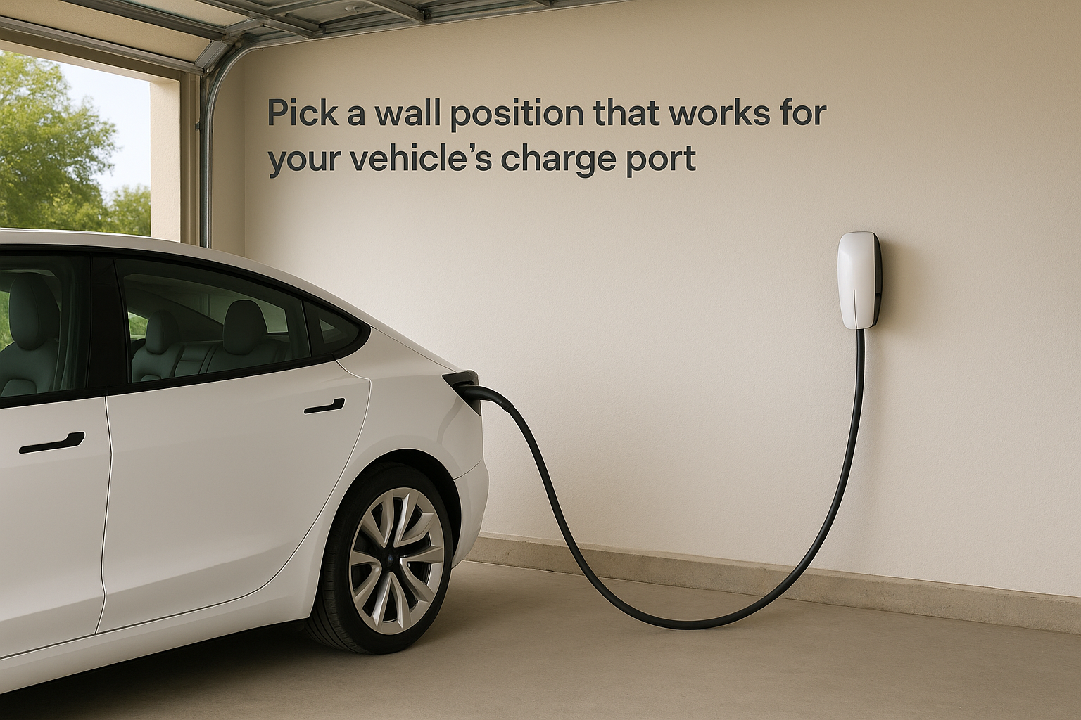
Mount the connector between 36 and 48 inches from the floor so the cable hangs naturally without pooling on the ground or pulling tight against the inlet.
Measure the conduit run from the panel to the mount point
The tesla wall connector installation manual specifies conduit entry points at the bottom of the unit, so your cable path must approach from below unless you use the knockout options on the back of the enclosure. Walk the full route from your electrical panel to the mount point and measure every segment, including vertical drops, horizontal runs along the wall, and any turns. Add 10 percent to your total measurement to account for bends and connectors, then confirm that wire length against the gauge and voltage drop calculations you will complete in the next step.
A clear path with minimal bends also reduces pulling tension on the conductors, which protects insulation during installation. It also keeps future service work straightforward when a technician needs to trace or replace a conductor.
Step 4. Choose breaker size, wire size, and conduit path
The electrical specs in the tesla wall connector installation manual point you toward the right components, but the NEC’s 80 percent continuous load rule is the calculation that drives every decision in this step. The Wall Connector draws up to 48 amps continuously, and a continuous load by code must not exceed 80 percent of the breaker’s rated capacity. That math produces a single answer: you need a 60-amp, two-pole breaker to feed a Wall Connector configured at its full 48A output.
Size the breaker and confirm panel capacity first
Before you order wire or conduit, open your main electrical panel and count the available slots. A 60A two-pole breaker occupies two adjacent slots and requires a panel with enough total capacity to absorb the added load. If your panel is already heavily loaded, a licensed electrician will need to review the load calculation before you commit to a 60A circuit. Downsizing the breaker to 50A and dialing the Wall Connector back to 40A is a valid option when panel capacity is tight, and it still gives you roughly 28 to 30 miles of range added per hour for most Tesla models.
If your panel does not have two adjacent open slots, a tandem breaker or subpanel addition is a better path than squeezing conductors onto an undersized circuit.
Match wire gauge to your breaker and run length
A 60A circuit requires 6 AWG copper wire at minimum for standard run lengths. If your conduit run from the panel to the mount location exceeds 50 feet, calculate voltage drop using your total run length, and upgrade to 4 AWG copper to keep drop under 3 percent. Voltage drop above that threshold causes the charger to operate outside its rated parameters and can shorten component life.
For conduit type, EMT conduit works well for indoor and protected outdoor runs and is the standard choice in most garage installations. Use Schedule 40 PVC where the conduit runs underground or through concrete. Pull three conductors: two hot legs and one ground. Gen 3 does not need a neutral, so you only pull three wires total on a new circuit dedicated to that unit.
Step 5. Mount the unit and land the conductors cleanly
With your conduit pulled and conductors in place, the physical installation comes down to two tasks: getting the bracket level on the wall and connecting each conductor to its correct terminal at the right torque. Both tasks are straightforward, but rushing either one causes problems that only show up weeks later under load.
Attach the mounting bracket before you pull wire through
The Wall Connector ships with a mounting bracket that must be secured to the wall before you feed conductors into the enclosure. Hold the bracket against the wall at your planned height, use a level to confirm it sits perfectly horizontal, and mark each mounting hole. For drywall over wood studs, drive screws directly into the studs on at least two of the four mounting points. If your mount surface is concrete or cinder block, use sleeve anchors rated for the connector’s weight rather than plastic anchors, which can work loose over time from vibration.
Feed conductors through the conduit entry point at the bottom of the enclosure before you hang the Wall Connector body on the bracket, not after, since the unit covers the entry once it seats on the mount.
Land the conductors and torque every terminal to spec
Open the tesla wall connector installation manual for your specific generation and locate the wiring diagram and torque specification table before you touch a terminal. Gen 2 requires connections to line 1, line 2, neutral, and ground terminals. Gen 3 and the Universal Wall Connector only require line 1, line 2, and ground since no neutral conductor is needed. Strip each conductor to the length shown in the manual, typically 5/8 inch, and insert it fully into the terminal block before tightening.
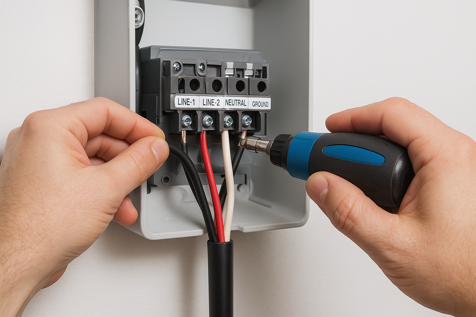
Torque values in the manual are not suggestions. Under-torqued terminals create resistance, which generates heat at the connection point and can damage the conductor or the terminal block over time. Use a calibrated torque screwdriver set to the value specified for your generation. After torqueing, tug each conductor firmly to confirm it is fully seated, then reinstall the front cover before restoring power.
Step 6. Commission Gen 3 and Universal in the Tesla One app
Once you restore power to the breaker, a Gen 3 or Universal Wall Connector will not deliver any charge until you complete commissioning through the Tesla One app. This is the step that trips up the most first-time installers because the tesla wall connector installation manual mentions it briefly but doesn’t walk you through the exact app flow. The Wall Connector’s LED will pulse white, indicating it is waiting for setup, and it will stay in that holding state until you finish the steps below.
Do not restore power until all conductors are fully seated and torqued and the front cover is reinstalled, since the app commissioning sequence requires the unit to be live.
Download the app and locate your serial number
Install the Tesla One app on your smartphone from the Apple App Store or Google Play Store, then sign into your Tesla account. If you don’t have an account, create one at tesla.com before installation day so you aren’t creating credentials on a job site. Open the app, tap the “+” icon to add a new device, and select “Wall Connector” from the product list. The app will prompt you to enter the serial number, which you photographed back in Step 1 from the label inside the enclosure. Type it in exactly as printed, since the app will reject partial matches.
Walk through the commissioning sequence step by step
The app guides you through a short sequence of screens that confirm your Wi-Fi network, set the maximum charging current, and register the unit to your account. Follow each prompt in order:
- Connect the Wall Connector to your 2.4 GHz or 5 GHz home Wi-Fi network when prompted
- Set the maximum current to match your breaker sizing from Step 4 (48A for a 60A breaker)
- Confirm the installation address for Tesla’s records
- Tap “Finish Setup” to complete registration
The LED will shift from pulsing white to solid green once commissioning succeeds, which confirms the unit is ready to charge your vehicle.
Step 7. Configure Wi-Fi, access controls, and power sharing
After commissioning completes, the Tesla One app opens a configuration menu where you control three distinct settings: network preferences, who can charge on your unit, and how the Wall Connector shares power when multiple units run on the same circuit. Each setting lives in a separate area of the app, so work through them in order rather than jumping between screens. The tesla wall connector installation manual covers the hardware side thoroughly but leaves most of the app-level configuration to the in-app prompts, which is why this step deserves its own breakdown.
Confirm and strengthen your Wi-Fi connection
Your Wall Connector needs a stable connection to your home network to receive firmware updates and report charging data to your Tesla account. Inside the Tesla One app, navigate to your Wall Connector’s device settings and check the signal strength indicator. A signal below two bars at the charger’s location will cause intermittent disconnections and failed updates.
If your garage sits far from your router, add a Wi-Fi extender or mesh node inside or near the garage before finalizing the network configuration, since a weak signal now becomes a recurring maintenance issue later.
Control who can charge on your unit
The app gives you two access modes for the Wall Connector: “All vehicles” allows any Tesla to initiate charging without restriction, while “Only my vehicles” locks the charger to vehicles linked to your Tesla account. For a private residence, the restricted mode is the better default since it prevents a neighbor or visitor from using your charger without permission. Toggle between modes in the “Access” section of the device settings screen.
Set up power sharing for multiple Wall Connectors
If you install more than one Wall Connector on a single circuit, the power sharing feature distributes available amperage across all active units automatically. In the app, open “Power Sharing Settings” and enter the total circuit amperage from your breaker, which is 60A if you followed Step 4. The units negotiate load balance over Wi-Fi with no additional hardware required on Gen 3 or Universal models. Confirm each unit appears in the power sharing group before you close this screen.
Step 8. Verify operation and document the final settings
Before you consider the installation complete, connect your Tesla and run a real charge session to confirm the Wall Connector delivers power at the amperage you configured. A commissioning screen that shows success in the app is not the same as a verified, load-tested circuit. This step catches any terminal connection issues, voltage drop problems, or setting mismatches before they surface at an inconvenient moment.
Run a full charge cycle and check the LED state
Plug your Tesla into the Wall Connector and watch the LED indicator on the front of the unit for the first 30 seconds. A solid blue LED confirms the vehicle accepted the connection and charging is active. Open the Tesla app on your phone and verify that the session shows the correct amperage, matching the maximum current you set during commissioning. If the app reports a lower amperage than expected, recheck your breaker size setting in the Tesla One app and confirm the vehicle’s onboard charger limit is not restricting the session.
Let the vehicle charge for at least 15 to 20 minutes, then place your hand near the conduit entry at the bottom of the Wall Connector. Warmth is normal. Heat that you cannot hold your hand near indicates a loose terminal connection or an undersized conductor, and you need to shut down the circuit and recheck your work before continuing.
A charge session that starts correctly and holds steady amperage for 20 minutes is strong evidence that your wiring and configuration are both correct.
Record every setting in a permanent log
Documenting your final configuration protects you if the Wall Connector ever needs service or replacement. Keep this record in a physical location near the panel and in a digital note linked to your Tesla account. Use the template below as your baseline:
| Setting | Value |
|---|---|
| Generation | Gen 2 / Gen 3 / Universal |
| Serial number | |
| Circuit breaker size | A |
| Wire gauge | AWG |
| Max charging current (configured) | A |
| Wi-Fi network name | |
| Access mode | All vehicles / Only my vehicles |
| Power sharing enabled | Yes / No |
| Install date | |
| Permit number |
This log also serves as your reference if you ever need to revisit the tesla wall connector installation manual for a firmware update or panel upgrade.
Step 9. Troubleshoot LED codes and common install issues
When something goes wrong after installation, the Wall Connector’s LED indicator is your first and most reliable diagnostic tool. Each LED pattern points to a specific category of problem, which means you can read the light before you open the tesla wall connector installation manual or call for support. Starting with the LED saves time and prevents unnecessary disassembly.
Read the LED pattern before you touch anything
The LED on the front of the unit communicates status through color and behavior, not just on or off. Match what you see to the table below to identify the issue before you take any action.
| LED Pattern | What It Means | First Action |
|---|---|---|
| Pulsing white | Awaiting commissioning | Complete Tesla One app setup |
| Solid green | Ready, not charging | Plug in and test |
| Solid blue | Charging normally | No action needed |
| Pulsing blue | Scheduled charge active | Check vehicle app settings |
| Solid amber | Reduced current warning | Check breaker size and wire gauge |
| Pulsing amber | Wi-Fi connection lost | Check router and signal strength |
| Solid red | Ground fault or wiring fault | Shut off breaker, inspect terminals |
| Pulsing red | Internal error | Power cycle once, then contact Tesla support |
A solid red LED always requires you to shut off the breaker and inspect every terminal connection before restoring power.
Fix the most common wiring and setup mistakes
The three issues that appear most often after installation are loose terminal connections, an incorrect maximum current setting, and a failed Wi-Fi link. A loose terminal produces amber or red LED behavior under load but may appear fine at low amperage, so always recheck torque values from your generation’s wiring diagram if the LED shifts during an active session.
Incorrect current settings show up as charging sessions that run below the amperage your vehicle requests. Open the Tesla One app, navigate to your Wall Connector’s device settings, and confirm the maximum current matches 80 percent of your breaker rating. A lost Wi-Fi connection produces pulsing amber and blocks firmware updates, so position a mesh node or extender within range of the charger if your garage sits far from your router.
Next steps
You now have everything you need to work through a Tesla Wall Connector installation from planning to verified operation. The tesla wall connector installation manual for your specific generation covers the core hardware details, but this guide fills in the gaps around permit requirements, wire sizing decisions, app commissioning, and LED troubleshooting that the official documentation leaves incomplete. Review each step before your installation date so there are no surprises on the day the work begins.
Putting this into practice still requires a licensed electrician for the panel connection and a permit from your local building department before any conductors are landed. If you are in Florida and want a team that installs Wall Connectors regularly with full in-house electricians and zero subcontractors, get a free EV charger installation quote from Advance Solar & Spa. With over 40 years of hands-on installation experience and Tesla Certified Installer status, we handle every part of the process so your charger works correctly from the very first plug-in.