Your Fronius Primo inverter is one of the most reliable single-phase string inverters on the market, until something on the display doesn’t look right and you need answers fast. Whether you’re configuring settings after a fresh install, troubleshooting an error code, or performing a factory reset, having quick access to the Fronius Primo inverter manual information saves real time and frustration. The problem is that official PDF manuals run hundreds of pages, and finding the one section you actually need can feel like searching for a needle in a haystack.
At Advance Solar & Spa, we’ve installed and serviced thousands of solar energy systems across Florida since 1983. Our technicians work with Fronius Primo inverters regularly, both the original SnapINverter line and the newer GEN24 Plus models, so we know exactly which settings homeowners ask about most and which error codes cause the most confusion. We built this guide from that hands-on experience.
This article breaks down the key sections of the Fronius Primo manual into plain, actionable steps. You’ll learn how to navigate the inverter’s menu system, understand common status and error codes, adjust critical settings, and walk through a proper reset procedure. We’ve also included direct links to official Fronius documentation so you can download the full PDF manuals when you need them. Consider this your practical companion to the manufacturer’s manual, minus the 300 pages you don’t need right now.
What you need before you start
Before you open a menu or touch any setting, gather everything you’ll need upfront. Working with your Fronius Primo inverter manual information without the right preparation leads to wasted time, and in some cases, it leads to configuration errors that take longer to undo than they would have taken to avoid. This section covers what to collect, what to know, and what safety steps to follow before you go any further.
The information you need to collect
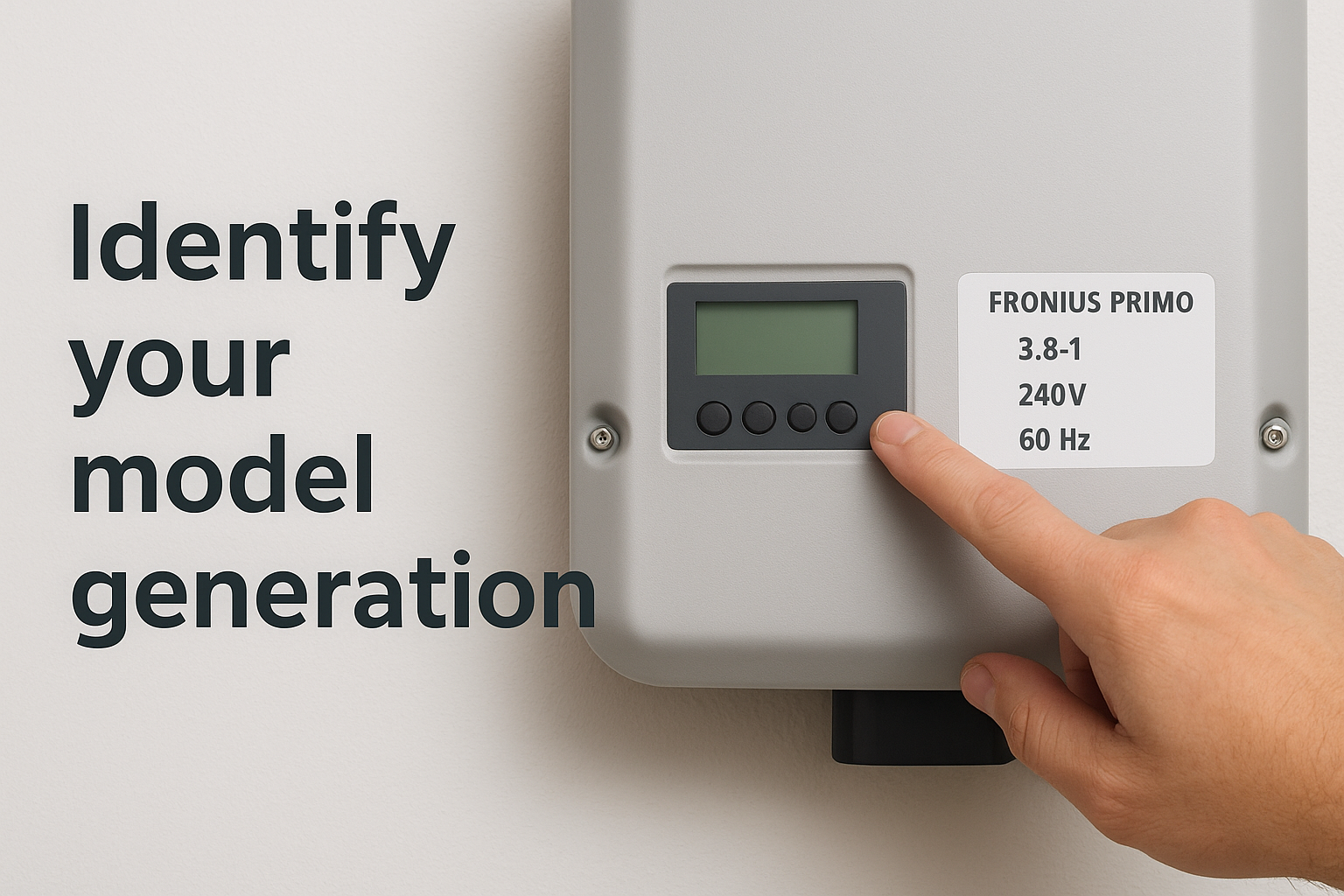
Your inverter’s model number and serial number are the two most important pieces of data you need before anything else. You’ll find both on the label attached to the right side of the inverter housing. The model number tells you which generation of Primo you have, either the original SnapINverter or the newer GEN24 Plus, and the serial number is required if you ever need to register the unit, download firmware, or contact Fronius support.
Write down your serial number and store it somewhere outside the inverter room, such as a home maintenance folder or a notes app on your phone, so you have it available if the unit needs service.
You also need to know your utility grid settings. In Florida, most utilities require inverters to be set to a specific frequency and voltage configuration. Your installer should have documented these at commissioning, but if they didn’t, your utility company can provide the correct parameters. Do not change grid settings without written confirmation from your utility.
Physical access and display readiness
Physical access to the inverter means you need to be standing in front of the unit with the display visible. The Fronius Primo display is located on the front panel, and you navigate it using the buttons directly below the screen. On the original SnapINverter models, you’ll find four navigation buttons. On the GEN24 Plus, the interface uses a touchscreen panel, so the navigation method differs from older units.
Make sure the inverter is powered on and in normal operation before you start navigating menus. You should see the green LED lit on the front panel and the display active. If the unit is in night mode because DC input is too low, some menus will still be accessible, but live production data will not display until sunlight is sufficient.
Network credentials and monitoring access
If you plan to configure Wi-Fi or LAN connectivity during this session, have your home or business network credentials ready before you start. The Fronius Primo connects to the Fronius Solar.web monitoring platform, and you’ll need your SSID and Wi-Fi password to complete that setup. If you’re on a business network with MAC address filtering or a managed firewall, contact your IT administrator before you begin the connection process.
You should also have access to either the Fronius Solar.web app or the local web interface of the inverter. The local interface runs at the IP address your router assigns to the inverter. Check your router’s connected device list to find it, or read it directly from the inverter’s COMM menu after the network connection is established.
| Item | Where to find it |
|---|---|
| Model number | Label on right side of inverter housing |
| Serial number | Same label, below the model number |
| Grid parameters | Commissioning document or your utility provider |
| Wi-Fi credentials | Router label or network administrator |
| Local IP address | Router device list or inverter COMM menu |
Step 1. Confirm your Primo model and specs
Fronius has produced two distinct generations of the Primo, and the manual, firmware, and menu structure differ significantly between them. Before you look up any setting or error code from the Fronius Primo inverter manual, you need to know exactly which unit you have. Getting this wrong means following instructions that don’t match your hardware, which wastes time and can produce incorrect configurations.
Identify your model generation
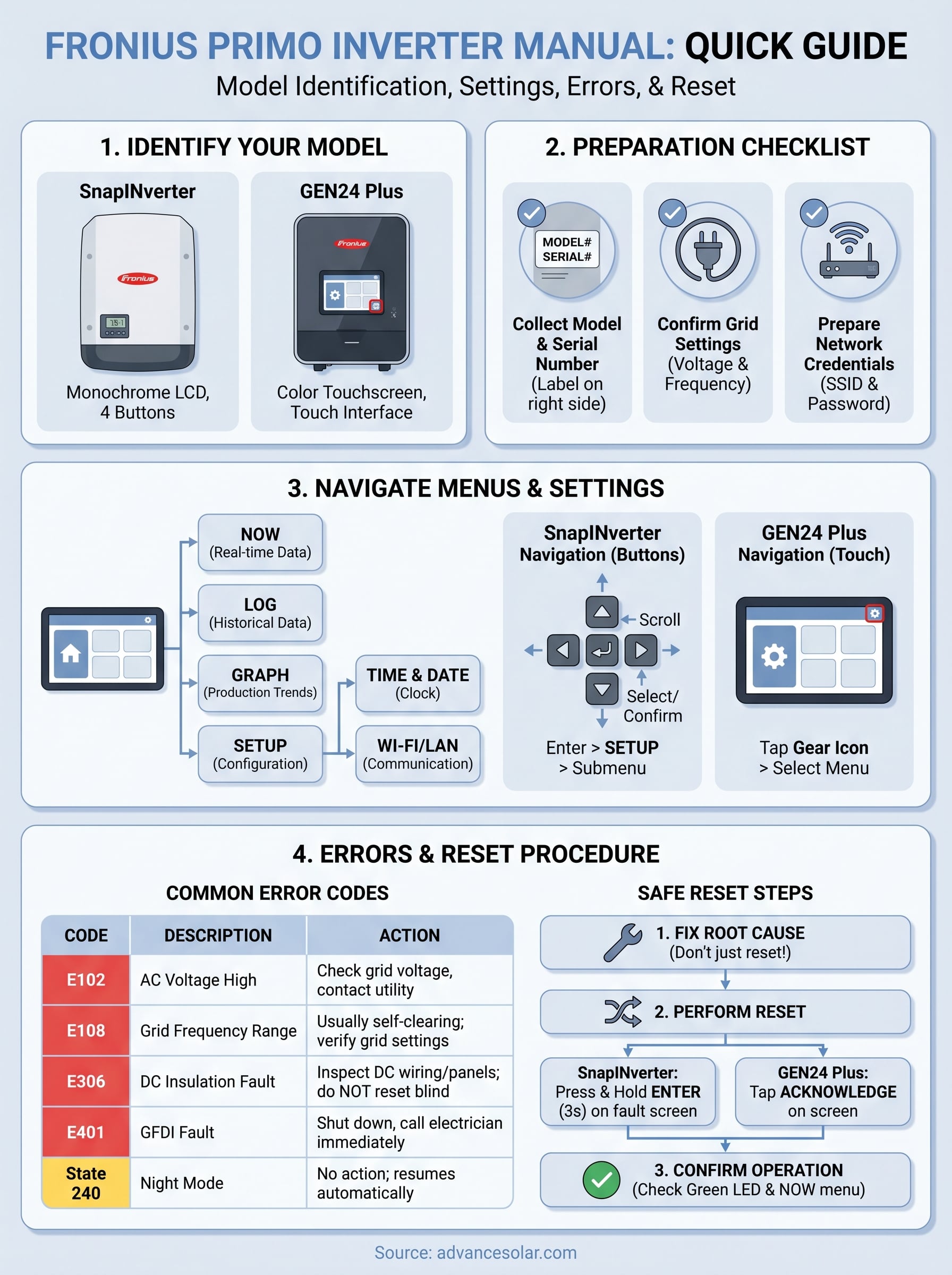
The clearest way to determine your generation is to check the model name printed on the rating label, which Fronius places on the right side of the inverter housing. If the label reads "Fronius Primo" followed by a power rating like 3.8-1, 5.0-1, or 15.0-1, you have the original SnapINverter generation, which uses a four-button navigation interface and a smaller monochrome display. If your unit reads "Fronius Primo GEN24 Plus," you have the newer model with a full-color touchscreen and a different menu system entirely.
| Model Generation | Display Type | Navigation Method | Common Power Ratings |
|---|---|---|---|
| Fronius Primo SnapINverter | Monochrome LCD | Four physical buttons | 3.8 kW to 15.0 kW |
| Fronius Primo GEN24 Plus | Color touchscreen | Touch interface | 3.0 kW to 10.0 kW |
If the label on your unit is faded or damaged, you can also identify the generation by the physical housing: the SnapINverter has a white enclosure with a flip-open panel, while the GEN24 Plus has a darker, more compact enclosure with a flush-mounted screen.
Read the nameplate specs
Once you know your generation, record the full model number, rated output power in kW, and the serial number from the same label. The serial number begins with a letter that indicates the manufacturing year, followed by a numeric sequence. Fronius uses this number to verify warranty status and to match your unit to the correct firmware versions, so store it somewhere accessible outside the equipment room.
You should also note the grid connection voltage and frequency ratings listed on the nameplate, typically 240V and 60Hz for Florida installations. These specs confirm that your unit was configured for the US grid standard, which matters when you cross-reference settings in the documentation or contact Fronius technical support with a configuration question.
Step 2. Locate the official manual for your unit
Fronius publishes all of their technical documentation through their official support portal at solar.fronius.com. Every version of the Fronius Primo inverter manual is available there, organized by product line and generation. The most common mistake people make is downloading the wrong document, specifically grabbing the SnapINverter manual when they own a GEN24 Plus, or pulling a regional version written for a different grid standard. Confirming your model in Step 1 prevents that problem before it starts.
Find the correct document on Fronius’s website
Go to solar.fronius.com and navigate to the Downloads section. Use the product filter to select your inverter model, either "Primo" or "Primo GEN24 Plus," then filter by document type to show only Operating Instructions or Installation Instructions. Fronius organizes documentation by language and document version, so select "English" and look for the most recent version number listed. If multiple revisions appear, download the latest one unless your installer specifically noted a firmware version that corresponds to an older document.
The table below shows the main documents available and what each one covers:
| Document Title | Who needs it | What it covers |
|---|---|---|
| Operating Instructions | Homeowners and technicians | Menu navigation, settings, error codes, reset |
| Installation Instructions | Licensed installers | Wiring, mounting, commissioning |
| Quick Reference Guide | First-time users | Basic startup and LED status |
| Datasheet | Anyone reviewing specs | Electrical ratings, efficiency curves |
Download and save the PDF before you need it
Once you find the correct document, download the PDF directly to a device you can access at the inverter location, whether that’s a phone, tablet, or laptop. Saving it locally matters because you may not have reliable internet access in a garage, utility closet, or exterior equipment enclosure when you actually need it most.
Store a printed copy of the quick reference guide near the inverter itself so any technician who services the system in the future can reference it without needing to search online.
Rename the file when you save it to something specific, such as "Fronius_Primo_GEN24_Operating_Instructions_EN_v1.pdf", so you can locate it quickly later. If you manage multiple properties or systems, create a dedicated folder for each one and include the inverter serial number in the folder name so documents never get mixed up across systems.
Step 3. Read LEDs, status, and basic screens
Before you navigate any menus, you need to understand what the LED indicators and default display screens are telling you. The Fronius Primo communicates system status visually before you ever press a button, and reading those signals correctly tells you whether the inverter is operating normally or flagging a condition that needs attention. This is the foundation of any diagnostic process covered in the Fronius Primo inverter manual.
Understanding the LED indicators
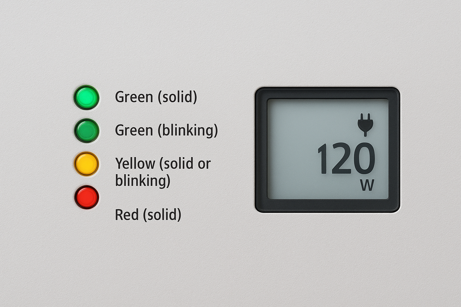
The LED panel on the front of your inverter uses three colored indicators to communicate operating status at a glance. Each color maps to a specific condition, and knowing them saves you time before you even look at the display screen.
| LED Color | Status | What it means |
|---|---|---|
| Green (solid) | Normal operation | Inverter is producing power and feeding the grid |
| Green (blinking) | Startup or reduced output | DC voltage present but output not yet at full capacity |
| Yellow (solid or blinking) | Warning | A non-critical event is active; check the display for a code |
| Red (solid) | Fault | Inverter has shut down; an error code will appear on screen |
| No LED | Night mode or no DC input | Inverter is offline due to insufficient sunlight |
A yellow LED does not always mean something is broken. It frequently indicates a grid event or a communication alert that clears on its own once conditions return to normal.
Reading the default home screen
When your Fronius Primo SnapINverter is running normally, the home screen cycles through key production data automatically. You will see current AC power output in watts, daily energy yield in kilowatt-hours, and a status bar at the top indicating grid connection. You do not need to press any buttons to see this information since the display rotates through these values on its own.
The GEN24 Plus home screen works differently because it uses a touchscreen layout with tiles that show live production data, grid feed-in, and battery state if storage is connected. Tap any tile to expand the detail view for that specific value. If you see a message on the home screen that reads "Service Required" or displays a three-digit number preceded by the letter "E," that is an error code, and you should move directly to Step 7 of this guide for the corresponding fix.
Step 4. Navigate NOW, LOG, GRAPH, and SETUP
The Fronius Primo SnapINverter organizes its information into four primary menu sections: NOW, LOG, GRAPH, and SETUP. Every piece of data you need for monitoring, diagnostics, and configuration lives in one of these four areas. Understanding how each menu is structured lets you find what you need without cycling through unrelated screens, which is especially useful when you are cross-referencing information from the Fronius Primo inverter manual during a service call or troubleshooting session.
The NOW and LOG Menus
NOW is your real-time dashboard. It displays current AC power output in watts, DC input voltage and current from your panels, grid frequency, and the inverter’s internal temperature. You navigate to it by pressing the left or right arrow button from the home screen until the NOW label appears at the top of the display, then pressing the Enter button to drill in. Each value updates in real time, so you can watch power output climb or drop as cloud cover shifts.
LOG stores historical production data organized by day, month, and year. Use this menu to pull total energy yield figures for a specific time period or to verify that daily production aligns with what your monitoring platform shows. Navigate to LOG the same way you navigate to NOW, using the arrow buttons to scroll between top-level menu options. Once inside LOG, press Enter to select the time interval you want to review, then use the arrows to scroll through the recorded data.
If the LOG data on your inverter does not match what Solar.web shows, the most common cause is a gap in the Wi-Fi connection during that period, not an actual production loss.
The GRAPH and SETUP Menus
GRAPH displays a bar chart of energy production plotted over time, giving you a visual representation of output trends across the day, month, or year. Select the time scale using the arrow buttons after you enter the menu. This view is useful for spotting consistent dips in production at specific times of day, which can indicate shading issues or panel-level faults worth investigating further.
SETUP is where all configurable parameters live, including time, date, display settings, grid parameters, and communication options. You will spend the most time in this menu during initial commissioning and any time a setting needs to change. Steps 5 and 6 of this guide walk through the most important SETUP sub-menus in detail.
Step 5. Set time, date, and display options
Accurate time and date settings matter more than most homeowners realize. Your inverter uses these values to timestamp every production record stored in the LOG menu, and an incorrect clock means your historical data will not align with your utility billing periods or your Solar.web monitoring reports. Walk through this step during initial setup and any time the inverter loses power for an extended period, since some models reset the clock after a prolonged outage.
Setting the Time and Date on SnapINverter Models
From the home screen, press the Enter button to access the main menu, then use the arrow buttons to navigate to SETUP and press Enter again. Inside SETUP, scroll until you find the Clock submenu and select it. You will see separate fields for hours, minutes, day, month, and year. Press Enter to select a field, use the up and down arrow buttons to adjust the value, and press Enter again to confirm before moving to the next field.
Double-check your AM/PM setting if your display uses 12-hour format, since a 12-hour offset in your clock will misalign an entire day’s worth of logged production data with real-world timestamps.
Work through every field in order: hours, minutes, seconds, day, month, and year. Once all fields are confirmed, scroll to the Save option and press Enter. The display will return you to the SETUP menu when the save is complete, confirming the clock is active.
Adjusting Display Settings
The Fronius Primo inverter manual documents two display settings most homeowners overlook: screen timeout duration and display brightness. Both live inside the SETUP menu under the Display submenu. Screen timeout controls how long the backlight stays active after the last button press before the display dims to conserve power. The factory default is typically 20 seconds, which is short enough that the screen appears off during normal operation. Set it to 60 seconds if you want the display to stay readable while you are reviewing data nearby.
Brightness adjustment is straightforward on both the SnapINverter and GEN24 Plus models. On the SnapINverter, navigate to Display inside SETUP, select Brightness, and use the arrow buttons to move the level up or down on a scale from 1 to 10. On the GEN24 Plus, tap the Settings gear icon from the home screen, select Display, and drag the brightness slider to your preferred level. Save before exiting to apply the change.
Step 6. Configure Wi-Fi, LAN, and monitoring
Connecting your Fronius Primo inverter to your home or business network is what turns a standalone piece of hardware into a system you can monitor remotely and troubleshoot without standing in front of it. The Fronius Primo inverter manual covers this process across both the SnapINverter and GEN24 Plus models, but the steps differ enough between generations that using the wrong instructions creates confusion fast. Work through the correct set of steps below based on the model you confirmed in Step 1.
Connect to Your Wi-Fi Network on the SnapINverter
From the home screen, press Enter to open the main menu, navigate to SETUP, and scroll to the COMM submenu. Inside COMM, select WLAN, then choose Scan to let the inverter search for available networks. Your network’s SSID will appear in a list once the scan completes. Select it, press Enter, and then use the arrow buttons to enter your Wi-Fi password one character at a time. After confirming the final character, navigate to Connect and press Enter.
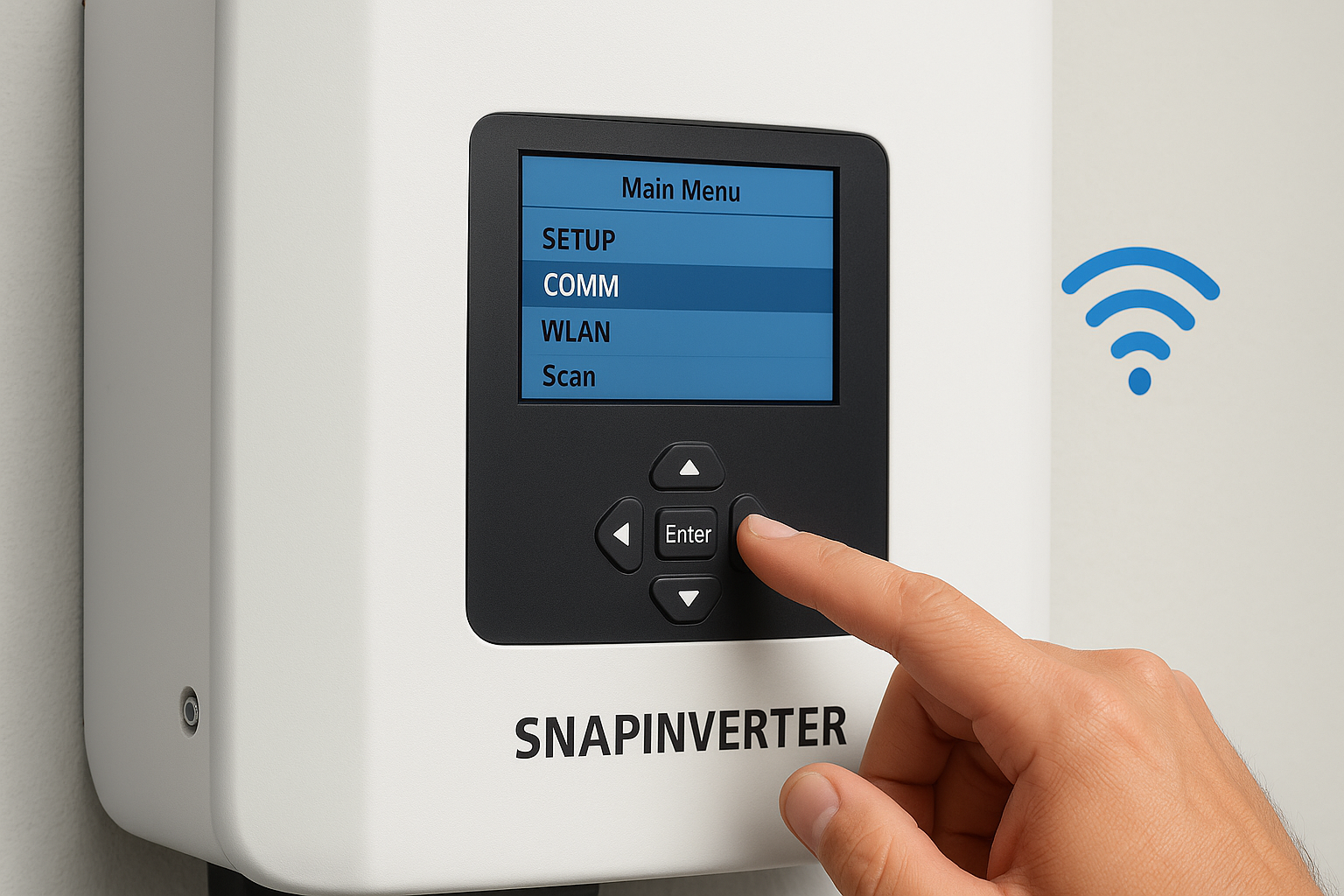
If your SSID does not appear in the scan results, move closer to your wireless router or access point, since the inverter’s built-in antenna has limited range through concrete walls or metal enclosures.
The inverter will display a connection confirmation message once it joins your network. Return to the COMM menu and select WLAN Status to verify the connection and note the IP address your router assigned to the unit.
Connect via LAN or Configure the GEN24 Plus
For a wired LAN connection, plug an Ethernet cable into the RJ45 port on the inverter’s data card and connect the other end to your router or network switch. On SnapINverter models, the inverter detects the wired connection automatically and you can confirm the assigned IP address in the COMM menu under LAN Status. No additional configuration is needed unless your network requires a static IP, which you can set inside the LAN submenu.
On the GEN24 Plus, tap the Settings gear icon from the home screen, select Communication, and then choose either WLAN or LAN depending on your connection type. The touchscreen walks you through each field in sequence, including IP mode, DNS settings, and subnet mask if you need a static configuration.
Verify Monitoring Through Solar.web
Once the inverter is connected to your network, open a browser on any device and go to solar.fronius.com to log into your Solar.web account. If you have not yet registered your inverter, select Add System and enter the serial number from the rating label to link your unit to your account. Production data typically begins populating within five to ten minutes of a successful network connection.
Confirm that the energy yield figures in Solar.web match what the LOG menu on your inverter shows for the same time period. A consistent mismatch between the two indicates a communication gap that is worth resolving before you rely on remote monitoring for system oversight.
Step 7. Fix common errors and status codes
Error codes on your Fronius Primo fall into two categories: state codes, which describe a temporary operating condition that clears on its own, and fault codes, which indicate a problem that requires action before the inverter returns to normal production. The Fronius Primo inverter manual lists every code in a dedicated appendix, but the table below covers the errors you are most likely to encounter in a Florida residential system so you can identify and address them without reading through hundreds of pages first.
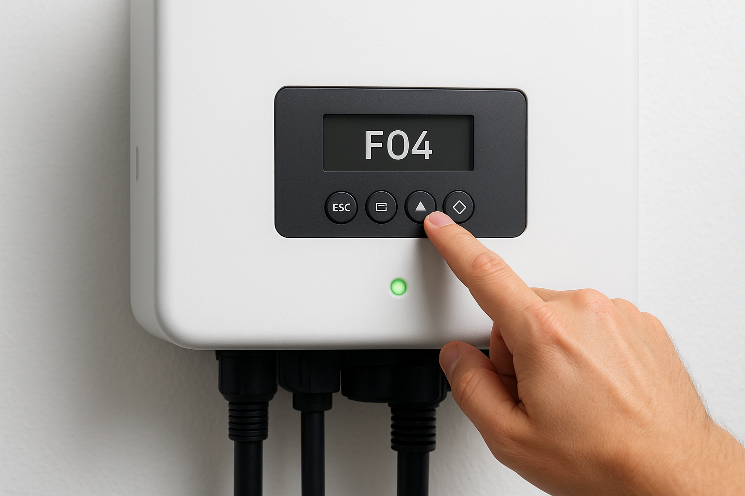
Read the Error Code Before Doing Anything Else
When your inverter shows a red LED or displays a code on screen, write down the exact code and the timestamp before you reset anything. Resetting without recording the error number removes the data you need to diagnose a recurring problem. On SnapINverter models, the code appears as a three-digit number preceded by the letter E on the main display. On GEN24 Plus models, the error code and a brief description appear directly on the touchscreen home tile.
If the same error code returns within 24 hours of clearing it, stop resetting the unit and contact a licensed solar technician, since repeated faults indicate a root cause that a reset will not fix.
Common Error Codes and What They Mean
Each code below corresponds to a specific condition, and the action column tells you exactly what to do. Do not skip the action step and rely on a reset alone, since most fault codes will return if the underlying condition is not resolved first.
| Code | Description | Action Required |
|---|---|---|
| E102 | AC voltage too high | Check grid voltage at the breaker; contact your utility if voltage exceeds 264V |
| E103 | AC voltage too low | Verify AC wiring connections and check for a tripped breaker |
| E108 | Grid frequency out of range | Usually self-clearing; if persistent, verify grid settings match utility requirements |
| E306 | Insulation fault on DC side | Inspect panels and DC wiring for damage; do not reset without a full DC inspection |
| E401 | GFDI fault | Shut down the system and call a licensed electrician immediately |
| State 240 | Night mode | No action needed; inverter will resume automatically at sunrise |
| State 307 | AC disconnect open | Verify the AC disconnect switch is fully closed |
Clear an Error After Fixing the Root Cause
Once you have addressed the underlying condition, press and hold the Enter button for three seconds on a SnapINverter model to acknowledge the fault and allow the inverter to attempt a restart. On the GEN24 Plus, tap Acknowledge on the error notification screen. The inverter will run through its startup sequence and reconnect to the grid automatically if conditions are within acceptable range.
Step 8. Reset safely and verify normal operation
A reset is not a fix by itself. It is a way to clear a logged fault after you have already addressed the root cause, and skipping the verification steps afterward means you have no confirmation that the inverter has returned to healthy operation. The Fronius Primo inverter manual describes this process across both model generations, and the procedure below consolidates those instructions into a clear sequence you can follow on-site.
Perform the Reset Procedure
Before you reset, confirm two things: the underlying fault condition has been corrected and the DC disconnect and AC breaker for the inverter are both in the closed position. If either disconnect is open, the inverter will fail to restart after the reset and display a new state code that may look like a second fault.
For the SnapINverter, press and hold the Enter button for three seconds while the fault code is displayed. The screen will clear and the inverter will run through its startup sequence automatically. For the GEN24 Plus, tap the Acknowledge button on the fault notification tile and allow the touchscreen to guide you through the restart confirmation. On either model, do not interrupt the startup sequence by pressing buttons or cycling power during the first 60 to 90 seconds after you initiate the reset.
If the inverter returns a fault code within minutes of a completed reset, stop and call a licensed solar technician rather than resetting again.
Confirm Normal Operation After Restart
Once the inverter completes its startup sequence, check the LED indicator on the front panel. A solid green LED confirms the unit has reconnected to the grid and is producing power. If the LED is blinking green, the inverter is still in startup mode and will stabilize within a few minutes as DC voltage from your panels rises to the operating threshold.
Navigate to the NOW menu and verify that AC power output, DC input voltage, and grid frequency all fall within expected ranges. For a standard Florida installation you should see grid frequency near 60Hz and AC voltage near 240V. If either value sits outside normal range, the inverter will disconnect from the grid on its own as a protection measure, and you will need to investigate the grid connection or contact your utility before the system will stay online.
Check your Solar.web dashboard after 10 minutes to confirm that live production data is flowing through correctly. A successful reset with verified monitoring output means the system is fully restored and operating normally.
What to do next
You now have a working reference for the most practical sections of the Fronius Primo inverter manual, covering model identification, documentation, menu navigation, error codes, and the correct reset procedure. Use this guide alongside the official Fronius PDF for your specific unit, and keep both accessible near your equipment so any technician who works on the system has what they need on hand.
Most settings and status codes you will encounter are manageable with the right information, but some faults, particularly DC insulation errors, GFDI faults, or repeated error codes, require a licensed professional rather than another reset. If your inverter is flagging issues you cannot resolve through the steps above, or if you want a full system inspection by certified technicians, contact the Advance Solar & Spa team. Our in-house staff has worked with Fronius systems across Florida for over 40 years and can get your system back to full production quickly.